Gravitational Waveforms

We analyze the gravitational waveforms from our numerical relativity simulations and compare them with the simulation done at LIGO. If the length of the interferometer arms is $L$, the strain $\frac{\delta L(t)}{L}$ on the arms due to the gravitational waveform is given by $$h \equiv \frac{\delta L(t)}{L}=F_{+}(\theta,\phi,\psi)h_{+}(t;\theta_{GW},\phi_{GW})+ F_{\times}(\theta,\phi,\psi)h_{\times}(t;\theta_{GW},\phi_{GW}),$$ where $F_{+}$ and $F_{\times}$ are antenna pattern functions determined by the orientation of the LIGO detectors with respect to the binary (see Fig. 1): $$F_{+}(\theta,\phi,\psi)=\frac{1}{2}(1+\cos^{2}\theta)\cos2\phi\cos2\psi -\cos\theta\sin2\phi\sin2\psi,$$ $$F_{\times}(\theta,\phi,\psi)=\frac{1}{2}(1+\cos^2\theta)\cos2\phi\sin2\psi +\cos\theta\sin2\phi\cos2\psi.$$
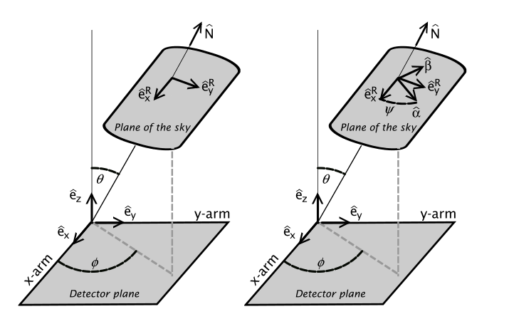
Fig. 1: The relative orientation of the sky and detector frames (left panel) and the effect of a rotation by the angle $\psi$ in the sky frame (right panel). (Reference: https://link.springer.com/article/10.12942/lrr-2009-2)
Here, $\theta_{GW}$ and $\phi_{GW}$ are the spherical coordinates of the observer from the binary's frame, taking the angular momentum of the binary to point along the z-axis. These values are tabulated below.
| Angle | Value | LIGO Ref |
|---|---|---|
| $\theta_{GW}$ | $\pi/6$ | https://dcc.ligo.org/public/0122/P1500218/01 2/GW150914_parameter_estimation_v13.pdf |
| $\phi_{GW}$ | 0 | Arbitrary |
To obtain $\theta$, $\phi$, and $\psi$ for calculating $F_{+}$ and $F_{\times}$, we need the find the orientation of the binary with respect to the observers. LIGO found that on September 14 2015, 09:50:45.39 UTC, the source position was consistent with: $$ \begin{align} \text{RA} &= 8\text{h} \\ \text{DEC} &= -70^{\circ} \end{align} $$
LIGO Ref: https://dcc.ligo.org/public/0122/P1500218/012/GW150914_parameter_estimation_v13.pdfThe location sites of the observatories are given and listed below.
| Detector | Latitude | Longitude | X-Arm Azimuth |
|---|---|---|---|
| LIGO Hanford | 46°27'19"N | 119°24'28"W | N 36°W |
| LIGO Livingston | 30°33'46"N | 90°46'27"W | W 18°S |
LIGO Ref: http://www.ligo.org/scientists/GW100916/GW100916-geometry.html
Using these values, we then calculate $\theta$ and $\phi$, and setting $\psi=0$.
| Detector | Angle | Value (rad) |
Ref | ||||||||||||
|---|---|---|---|---|---|---|---|---|---|---|---|---|---|---|---|
| LIGO Hanford |
|
|
|
||||||||||||
| LIGO Livingston |
|
|
|
Liu code can be found here
From this, we get $$ F_{+} = 0.7339 \\ F_{\times} = 0.1754 $$ Our simulation calculates $h_{+}^{NR}$ and $h_{\times}^{NR}$ at an extraction radius of $r_{ext}=4924.5M_{\odot}=7272\text{km}$. The luminosity distance between the source and LIGO has been observed to be $D_{L} = 410 \text{Mpc} = 1.265\times 10^{22} \text{km}$. Thus, we must scale our data to obtain the measured strain by LIGO: $$ h_{+} = \frac{r_{ext}}{D_{L}}h_{+}^{NR} = 5.7483\times 10^{-19} h_{+}^{NR}\\ h_{\times} = \frac{r_{ext}}{D_{L}}h_{\times}^{NR} = 5.7483\times 10^{-19} h_{\times}^{NR}\\ $$ The final equation for measuring the strain from our numerical simulation is then $$h \equiv \frac{\delta L(t)}{L} = 5.7483\times 10^{-19}\left(0.7339\, h_{+}^{NR}(t;\pi/6, 0) +0.1754 \, h_{\times}^{NR}(t;\pi/6, 0)\right) $$